 Application Note
Radome Thermal Insulation
 |
 |
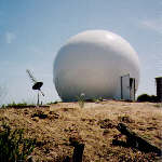 |
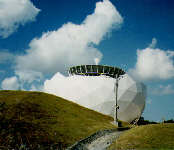
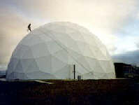
AFC manufactures six types of dielectric radomes. The six types identify themselves primarily by the radome wall construction. In each case, the dielectric panel edges are reinforced into flanges for adjacent panel assembly. The dielectric flanges form a framework known as a Dielectric Space Frame (DSF). Depending on radome wall parameters, adjacent panel flanges may also serve as environmental load bearing beams or struts. Each panel is a molded one piece unit. When assembled to the other panels, the panel array forms a truncated spherical surface. Individual panels may be doubly curved or flat yielding a faceted or spherically smooth appearance. Foam insulation is often added to the wall producing a two or three layer sandwich configuration. As required by sophisticated electrical performance requirements, inductive circuit elements may be laminated into the dielectric flanges to reduce scattering loss by using a process known as impedance matching.
The six DSF radome types are:
- The TM thin membrane wall radome where adjacent panel flanges carry all the environmental loads.
- The SL solid laminate wall radome.
- Adding a layer of foam to the inside wall DSF radome forms a 2L two layer sandwich. Foam thickness is chosen primarily for thermal insulation and cost objectives.
- The SFC three layer sandwich wall radome. Core thickness is chosen based on the wavelength for the highest RF signal frequency.
- The CLS and THS wall radome for simultaneously high frequency, Ka-band, broadband and very high wind structural performance.
 Compared to the TM wall, the 2L and SFC wall radomes have significant insulation value differences. When operating under extreme weather conditions, such differences need to be understood in characterizing radome heating and/or cooling requirements. While the 2L wall radome structural parameters supporting environmental wind loads and RF performance are independent of the foam thickness, the SFC version, on the other hand, is not. With the SFC, core thickness is determined by antenna system frequency. The higher the frequency, the thinner the core thermal insulation value.
In order to detail the insulation value of the 2L and SFC wall radomes, the two graphs characterize the amount of heat necessary to raise the internal radome temperature 50 degrees C. The 2L wall heat requirement is calculated for 0.5 and 2 inch foam insulation thickness for radome diameter from 12 to 48 foot diameter. In contrast, the SFC radome heat requirement is displayed for a 18 foot and 31 foot diameter radome with operating frequency determining the final core thickness value.
In choosing a radome type, the SFC radome is optimized for RF performance and, for the most part, has better RF performance over its 2L wall counterpart. Broad RF frequency bandwidth is characteristic of the 2L wall radome with foam thickness optimized for thermal insulation constraints. To enhance RF performance, impedance matching may be applied to both radome types.
At the same time, a 2L or SFC type radome is often deployed where air-conditioning or heating is considered a must (for example the hot, moist salt laden climate of a Pacific Ocean island). Under such circumstances, one can easily trade-off the lifetime air-conditioning or heating operating efficiency costs for the green value of the 2L or SFC radome. In fact, over of the course of the radome lifetime, the energy savings for the 2L and SFC radome are enough to pay for the radome iteslf.
An example of the energy efficiency trade-off is shown in the table below for a 52-ft. diameter TM wall dielectric radome and a 2L sandwich wall radome.
|
Assumption 2 KW Internal Heat Generation with Sun Load 400 Btu/Hr*ft2 |
2L Sandwich Wall Radome |
TM Thin Membrane Wall Radome |
|
Cooling for 50-degree F temperature reduction. |
55,000 Btu/Hr |
460,000 Btu/Hr |
|
Cooling for 25-degree F temperature reduction. |
39,000 Btu/Hr |
300,000 Btu/Hr |
From the table, the 2L sandwich wall can provide an 8-fold reduction in the capacity of the air-conditioner that would be required for effective climate control within the radome. Should climate control be part of the 20-year life-cycle solution, the 2L or SFC wall upgrade significantly reduces the operational power costs.
In all cases, the thermal insulation layer is an integral part of the manufacturing process forming a laminated one piece panel. These thermally insulated radome panels are then placed into AFC's anechoic chamber for RF electromagnetic specification compliance testing and characterization.
Note that all dielectric radome types often serve similar applications. Application requirements typically emphasize RF, environmental or cost concerns. These concerns then dictate radome type and in the final analysis, radome price.
AFC manufactures, markets and sells worldwide satellite dish antennas, radomes, antenna feeds and ultra low loss waveguide transmission line Tallguide �. Our customers serve the broadcast, communications, radar, weather and cable industry, defense, government, and government agencies worldwide. AFC's quality control manufacturing standards are certified under ISO 9001 : 2015.
Top of Page Return to AFC ProfileReturn to Radome Network Home Page.
Telephone (352) 687-4121 Fax(352) 687-1203 E-mail sales@afcsat.com
Tallguide is a Registered Trademark of Antennas for Communications Copyright � 1995 - 2020 Antennas for Communications